Note: Login password required to view technical guide contents of all chapters. Click Store to buy Lab Kit.
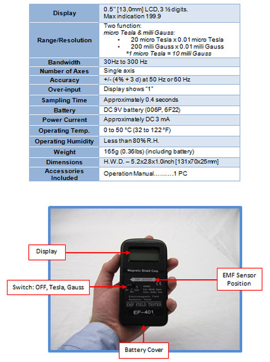
EF-401 Gaussmeter - Specifications & Instructions
A cost effective, handheld, single-axis AC magnetic field meter that provides quick & reliable measurements of electromagnetic field (EMF) radiation generated by external sources like power lines, electrical wiring, motors, audio/visual equipment and other devices.
No probe is required – just position this Gaussmeter in the affected area.
Specifications:
No probe is required – just position this Gaussmeter in the affected area.
Specifications:
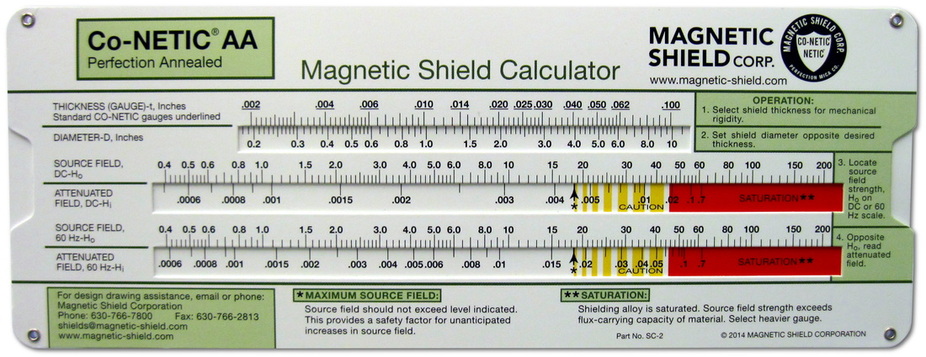
Magnetic Shield Slide-Rule Calculator - Problem-Solving Examples & Instructions
Note: The calculator is intended as a tool for estimating magnetic shielding requirements. Due to the unique circumstances that accompany each application, testing a prototype shield in actual working conditions is recommended to prove the design.
Calculation Examples:
A. What is the estimated attenuation of a 10" long, 0.040" wall cylinder, with 2 ½" diameter, in a 3 Gauss DC field?
Required steps:
1. Move the slide to align the 0.040" wall thickness on the uppermost scale opposite the 2 ½" cylinder diameter on the second scale.
2. Opposite the 3 Gauss point on the SOURCE FIELD-DC-Hoscale, read approximately 0.0014 Gauss on the ATTENUATED FIELD-DC-Hi scale. This signifies that the field inside the cylinder should be reduced to 0.0014 Gauss, or 1.4 milliGauss. The estimated attenuation factor is 3.0 / .0014 or 2143 times.
B. A magnetic shield 6" in diameter is required to operate in an 8 Gauss AC field. What wall thickness should be used to construct the shield?
Required Steps:
1. At the bottom of the slide rule, move the slide to align the arrow and asterisk that indicate the maximum source field to point to 8.0 on the SOURCE FIELD-60Hz-Ho scale. This provides a limit to the maximum flux density inside the walls of the cylinder, assuring that the operating point of the Co-Netic® AA Alloy remains below the saturation range for the given field.
2. Opposite the 6.0" diameter on the upper scale pair, read minimum wall thickness of 0.0265". Round the wall thickness up to 0.030", the next thicker standard size. The estimated attenuation factor of this shield is 8.0 / .018 or 444 times.
When choosing a shield wall thickness, recognize that the practicalities of metal fabrication may dictate use of shield wall thicknesses heavier than those found by the method above.
If higher attenuation factors are required, multiple layer shields may be necessary.
If the required shield is beyond the scales of this chart, multiple shield layers and/or combinations of Co-Netic® AA and NETIC® S3-6 shielding alloys may be required. Contact Magnetic Shield Corp. for technical assistance.
MATERIAL STANDARDS
| MIL-N-14411C.pdf |